
 Regular readers will be aware of my tragic addiction to all things Las Vegas. It’s been nearly six months since our last visit, and I am pining for bright lights and cocktails. Few things make a drink nicer than some coloured lights in the vicinity.
Dr Weasel, ever alert to the causes of his wife’s grumpiness, decided to cheer me up by making me an animated, brightly lit drinks coaster.
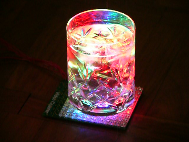
Here it is under a gin and tonic:
And here it is, glass-free, displaying a spinning galactic ice-cube.
The coaster can be driven from any PC with a serial port and will display any 10×10-pixel video you wish. Over to Dr Weasel for his version of a recipe (100% less lead-free than the recipes you’ll usually find here).
You will need:
30 1K 0805 resistors (R1 – R30)
30 MBTA42 NPN transistors (Q1 – Q30)
10 100 Ohm 0805 resistors (R31 – R40)
10 FMMT717 PNP transistors (Q31 – Q40)
5 74HC594 SOIC shift registers (IC1 – IC5)
4 100nF 1206 capacitors (C1 – C4)and finally:
100 TB5-V120-FLUX-RGB8000 RGB LEDs (LED00 – LED99)
The LEDs can be hard to get hold of at a decent price; eBay is once again the friend of the penurious electrical engineer.
Manufacture one or more PCBs using these Gerber and drill files. A double-sided PTH process is required, so it is probably best to use one of the various small-volume professional PCB manufacturers; I have found PCB Train in the UK to be fairly reliable. Assemble the board, taking great care when soldering the surface mount components. I found this one to be right at the limit of my dexterity.
Attach power and data cables to the connector in the bottom right of the board. Seen from above, we number the six pins:
1 2 3
4 5 6The corresponding signals are:
- XVOLTS – drive voltage for LEDs. Connect to 4V current limited supply.
- SERIAL_CLOCK – shift data from SERIAL_DATA on positive-going edge.
- SERIAL_LATCH – latch 40 bits from shift register to LED control on positive-going edge.
- GROUND – common ground.
- 5VOLTS – supply voltage for control circuitry. Connect to 5V supply.
- SERIAL_DATA – input data for shift register.
To scan the display, clock 10 4-bit numbers into the shift register. To clock in a bit:
- bring SERIAL_CLOCK low
- modify SERIAL_DATA
- bring SERIAL_CLOCK high
Once 40 bits have been clocked in, the SERIAL_LATCH signal can be brought high to transfer them to the LED control circuitry. Each 4 bit number selectively enables the red, green and blue LEDs in one row, and selectively disables all LEDs in one column. So if we clock in a string:
0011 0100 0111 ...
RGCB RGCB RGCBThis sets all the LEDs in row 0 to blue, all the LEDs in row 1 to green and all the LEDS in row 2 to cyan (green + red). It disables all the LEDs in columns 0 and 2. By rapidly clocking in various combinations of values (typically with only 1 of the 10 column-disable bits low), we can scan the array to build up an image, and use pulse-width modulation to give a range of apparent intensities.
This firmware can be used with an Atmel ATmega644 to generate the required signals in response to serial input from a PC or Mac.
A couple of words of warning. Modern LEDs can be very bright indeed. You could probably hurt yourself pretty badly by dialling them up to full intensity and ignoring your look-away reflex, so don’t. Also, when debugging your firmware it is easy to stall the scanning process and burn out the precious LEDs. Use a decent current-limited bench power supply, with the current dialled back to a few tens of milliamps to avoid this happening.
